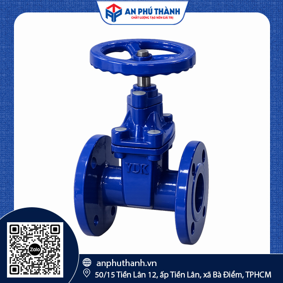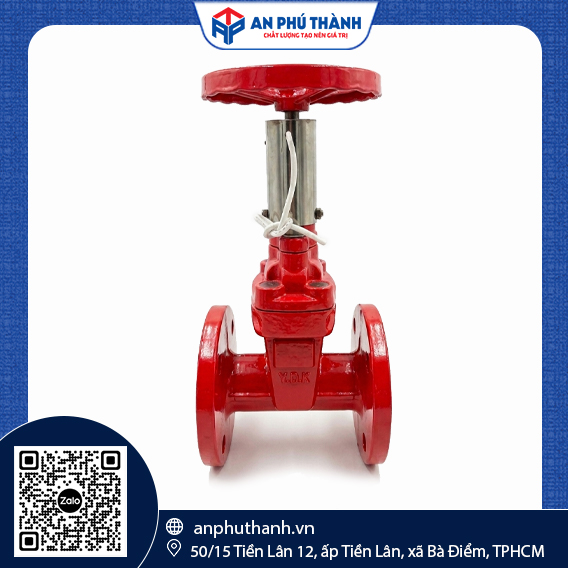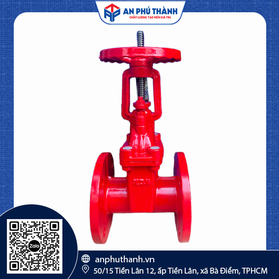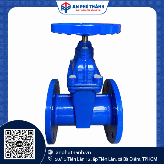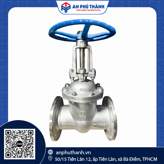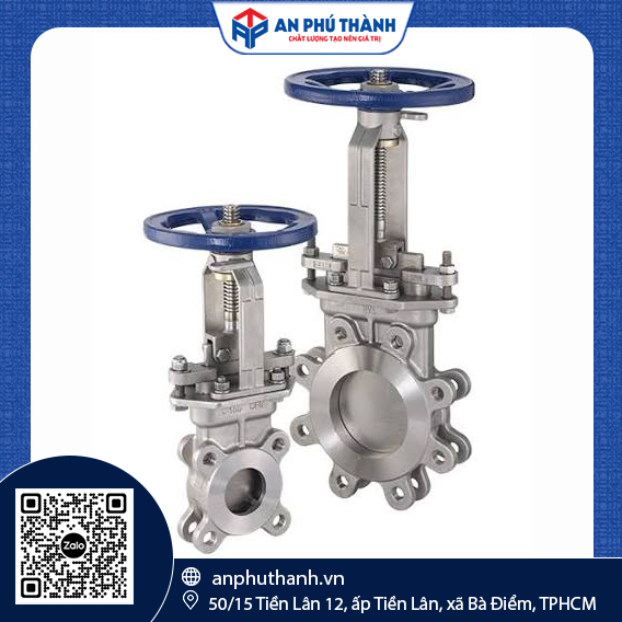
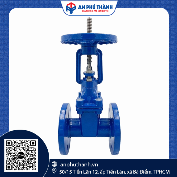
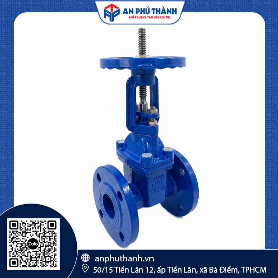


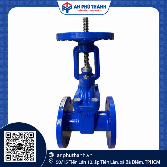
YDK Rising Stem Gate Valve | MODEL KRX-16
| Brand | Y.D.K |
| Model | KRX-16 |
| Pressure Standard | PN10, PN16 |
| Brand | BTL |
| Qrigin | China |
| Size | DN50 - DN600 |
| Design standards | BS 5163 |
| Working pressure | PN10/PN16 |
| Test pressure | 1.0 MPa (10 bar) |
| Refrigerant temperature | 80°C |
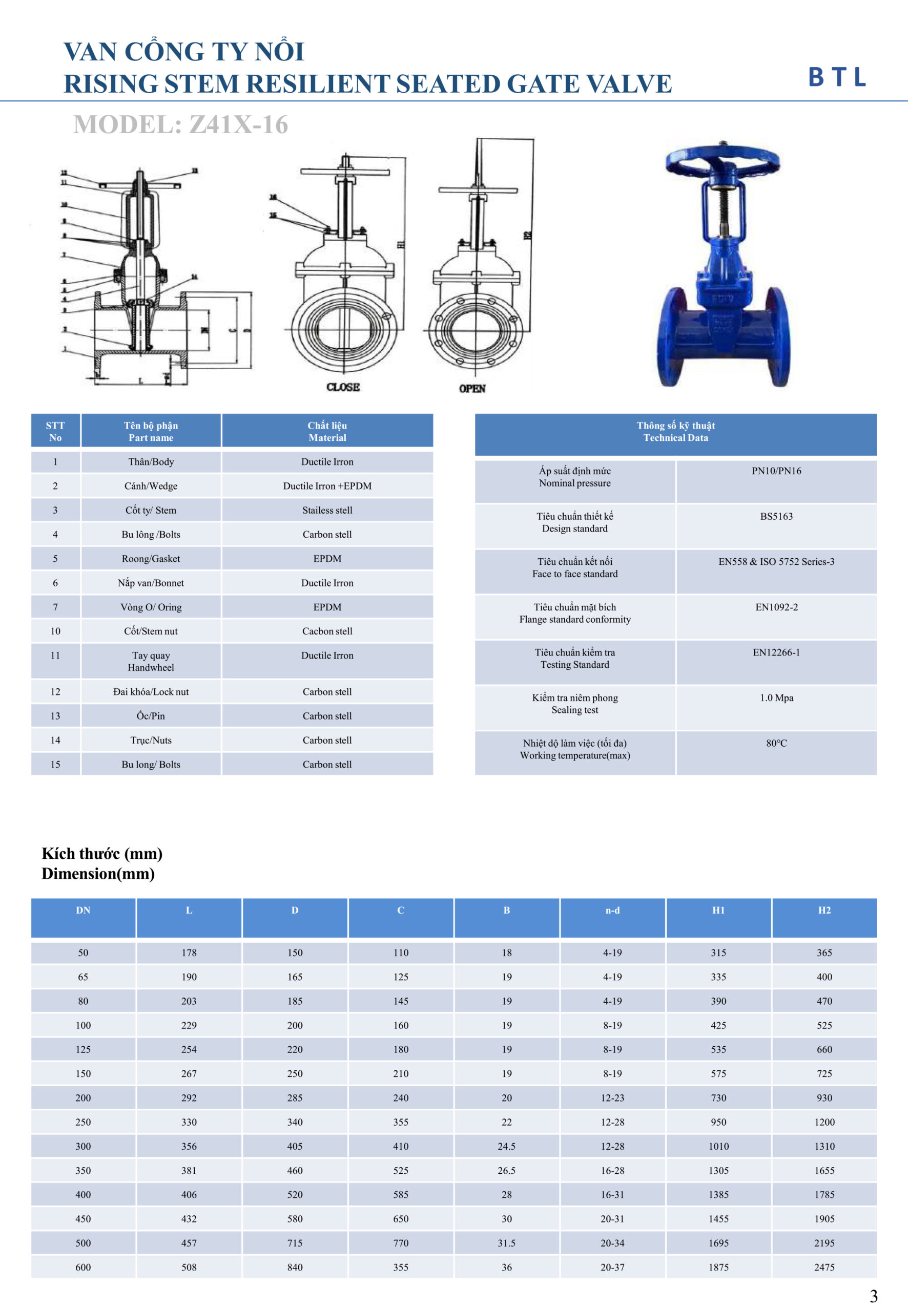
The BTL Z41X-16 Rising Stem Gate Valve is an industrial isolation valve featuring a rising stem design. During operation, the valve stem moves vertically upward or downward, allowing users to identify the valve’s open or closed status from a distance. This product complies with European design standards BS5163, EN558 & ISO 5752 Series-3 and is specifically designed for urban water supply and drainage networks, industrial park infrastructure, and fire protection pumping stations.
| No. | Component | Material | Function |
|---|---|---|---|
| 1 | Body | Ductile Iron | Main pressure-bearing body, housing the gate chamber and providing two ends for pipeline connection |
| 2 | Gate | Ductile Iron + EPDM | Flow-blocking disc, fully coated with EPDM rubber to ensure tight sealing when closed |
| 3 | Stem | Stainless Steel | Actuating stem that transmits rotational movement from the handwheel into the linear movement required to raise or lower the gate |
| 4 | Bolt | Carbon Steel | Connects the flanges and secures the structure |
| 5 | Gasket | EPDM | Provides sealing between the valve body joints |
| 6 | Valve Bonnet | Ductile Iron | Seals the body chamber and provides guidance and support for the vertical movement of the valve stem |
| 7 | O-Ring | EPDM | Seals around the valve stem and prevents leakage along the stem during operation |
| 10 | Stem Nut | Carbon Steel | Drives the valve stem and converts the handwheel’s rotational movement into axial thrust |
| 11 | Handwheel | Ductile Iron | Manual component used to open and close the valve, mounted on top of the valve stem |
| 12 | Locking Ring | Carbon Steel | Secures the handwheel to the stem and prevents loosening during operation |
| 13 | Nut | Carbon Steel | Positioning fastener for the transmission components |
| 14 | Shaft | Carbon Steel | Additional connecting component in the valve’s top drive assembly |
| 15 | Bolt | Carbon Steel | Connecting bolt for the bonnet/handwheel assembly |
| DN | L (mm) | D (mm) | C (mm) | B (mm) | n-d | H1 | H2 |
|---|---|---|---|---|---|---|---|
| 50 | 178 | 150 | 110 | 18 | 4-19 | 315 | 365 |
| 65 | 190 | 165 | 125 | 19 | 4-19 | 335 | 400 |
| 80 | 203 | 185 | 145 | 19 | 4-19 | 390 | 470 |
| 100 | 229 | 200 | 160 | 19 | 8-19 | 425 | 525 |
| 125 | 254 | 220 | 180 | 19 | 8-19 | 535 | 660 |
| 150 | 267 | 250 | 210 | 19 | 8-19 | 575 | 725 |
| 200 | 292 | 285 | 240 | 20 | 12-23 | 730 | 930 |
| 250 | 330 | 340 | 355 | 22 | 12-28 | 950 | 1200 |
| 300 | 356 | 405 | 410 | 24.5 | 12-28 | 1010 | 1310 |
| 350 | 381 | 460 | 525 | 26.5 | 16-28 | 1305 | 1655 |
| 400 | 406 | 520 | 585 | 28 | 16-31 | 1385 | 1785 |
| 450 | 432 | 580 | 650 | 30 | 20-31 | 1455 | 1905 |
| 500 | 457 | 715 | 770 | 31.5 | 20-34 | 1695 | 2195 |
| 600 | 508 | 840 | 355 | 36 | 20-37 | 1875 | 2475 |
Note: Product specifications for BTL products listed in the catalog are subject to change by the manufacturer without prior notice.
Similar to other types of gate valves, the BTL rising stem gate valve operates through the vertical movement of the valve stem to open or shut off the flow of the medium.
Due to its specific rising stem design, this type of valve must be installed in locations that meet two essential conditions: sufficient clearance above the valve and convenient visibility of its open/closed status. Common installation locations include:
Installation note: Rising stem gate valves are not suitable for installation in locations with low ceilings, shallow valve chambers, deep submerged pits, or underground applications. Limited space may not provide sufficient clearance for the valve stem during operation. In addition, high humidity can accelerate corrosion of the exposed stem, while dirt and sand may accumulate in the stem threads, causing the valve to become stuck.
An Phu Thanh is an authorized distributor of BTL rising stem gate valves, with a wide range of sizes from DN50 to DN600 readily available in stock. For consultation or a preferential quotation for your project, please contact our Hotline/Zalo at 0946 729 913 for a prompt response. An Phu Thanh is always pleased to accompany you in your construction projects and water supply and drainage pipe.
Do you need product advice or a quote? Leave your details, and the technical team at An Phu Thanh will contact you within 24 hours.