
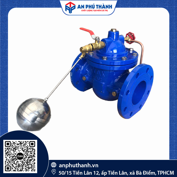
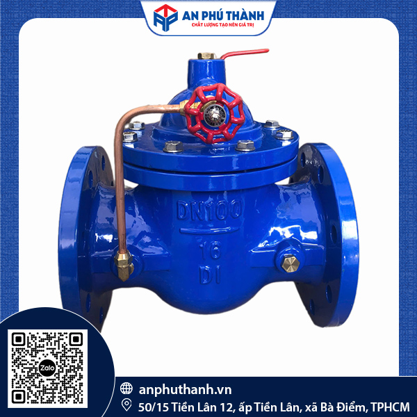


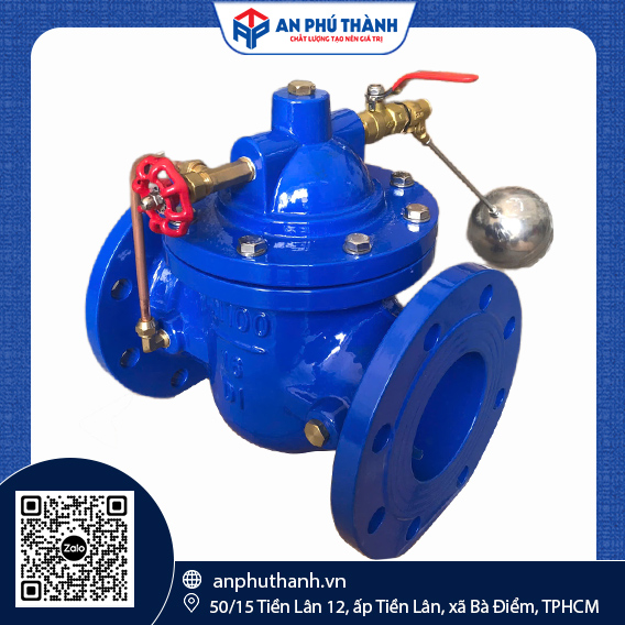
BTL FLANGED FLOAT VALVE | MODEL: 100X-16
| Brand | BTL |
| Model | 100X-16 |
| Pressure Standard | PN10 |
| Brand | YDK |
| Rated pressure | PN10 & PN16 |
| Flange standards | BS4504 |
| Shell testing | 2.4 MPa (24 bar) |
| Sealing test | 1.76 MPa (17.6 bar) |
| Maximum operating temperature | 80ºC |
In underground water storage tanks, rooftop tanks of high-rise buildings, and industrial reservoirs, automatic water level control to prevent overflow and protect pumps from running dry is essential. The YDK Hydraulic Float Valve – Model KCV100 uses a small float valve assembly (Pilot) combined with a main valve diaphragm to automatically open and close the water supply flow according to the actual water level, preventing both overflow and water depletion. At the same time, it helps the piping system operate smoothly without causing water hammer.
The YDK Float Valve, Model KCV100, consists of 16 main components, each made from quality materials to ensure effective operation.
| Component | Material |
| Body | GGG50 ductile iron with electrostatic Epoxy surface coating |
| Seat | Precisely machined brass, resistant to wear |
| Platen | Carbon steel CS |
| Seal | EPDM rubber for leak-proof sealing |
| Disc | GGG50 ductile iron |
| Diaphragm | Fiber-reinforced EPDM rubber |
| Platen | Carbon steel CS |
| Nut | Stainless steel |
| Stem | SS410 stainless steel |
| Spring | Stainless steel |
| Pilot Valve | SS304 stainless steel, pressure-sensing control |
| Bonnet | GGG50 ductile iron |
| Bolts | Stainless steel A2-70 (SS304) |
| Needle Valve | SS304 stainless steel, controls opening/closing speed |
| Globe Valve | SS304 stainless steel, used to isolate the control line during maintenance |
| Thread Float Valve | SS304 stainless steel, installed directly inside the tank to sense the water level |
Dimensional data for installation length and flange standards for Shop Drawing preparation:
| DN | L (mm) | D (mm) | D1 (mm) | b (mm) | n-d |
| 50 | 203 | 165 | 125 | 19 | 4 – 19 |
| 65 | 216 | 185 | 145 | 19 | 4 – 19 |
| 80 | 241 | 200 | 160 | 19 | 8 – 19 |
| 100 | 292 | 220 | 180 | 19 | 8 – 19 |
| 125 | 330 | 250 | 210 | 19 | 8 – 19 |
| 150 | 356 | 285 | 240 | 19 | 8 – 23 |
| 200 | 458 | 340 | 295 | 20 | 12 – 23 |
| 250 | 530 | 405 | 355 | 22 | 12 – 28 |
| 300 | 600 | 460 | 410 | 24.5 | 12 – 28 |
| 350 | 675 | 520 | 470 | 26.5 | 16 – 28 |
| 400 | 730 | 575 | 525 | 28 | 16 – 31 |
| 450 | 720 | 635 | 585 | 30 | 20 – 31 |
| 500 | 790 | 710 | 650 | 31.5 | 20 – 34 |
| 600 | 970 | 840 | 770 | 36 | 20 – 37 |
| 700 | 1120 | 910 | 840 | 39.5 | 24 – 37 |
| 800 | 1200 | 1025 | 950 | 43 | 24 – 40 |
The hydraulic float valve consists of two functional assemblies: the main valve installed on the water supply pipeline, and the pilot float assembly installed inside the water storage tank. The main valve features a diaphragm-operated disc, in which the chamber above the diaphragm is hydraulically connected to the float assembly through a signal line (pilot line).
The float assembly acts as a signal control valve (pilot valve) and does not directly apply mechanical force to the main valve disc.
When the liquid level in the tank falls below the preset level, the float arm moves with the float and opens the signal valve, reducing the pressure in the diaphragm chamber above the main valve. The resulting pressure differential between the supply pipeline (high pressure) and the diaphragm chamber (reduced pressure) generates an upward force that lifts the main valve disc, allowing flow to pass through and supply liquid to the tank.
When the liquid level rises to the preset level, the float rises and closes the signal valve, allowing pressure from the supply pipeline to flow back into the diaphragm chamber. The pressure in the chamber becomes balanced with or exceeds the flow pressure beneath the valve disc, causing the main valve disc to close tightly and stop the flow into the tank.
Through indirect control based on hydraulic pressure differential, the YDK hydraulic float valve can operate stably on pipelines with large nominal diameters (typically from DN50 to DN300) and under high-pressure conditions.
To ensure the YDK KCV100 hydraulic float valve operates accurately and without pressure surges, the following points should be considered before installation:
If you need consultation or a detailed quotation for the YDK Hydraulic Float Valve – Model KVC100 for your project, please contact An Phu Thanh via Hotline/Zalo: 0946 729 913. We are always ready to support you anytime, anywhere!
Do you need product advice or a quote? Leave your details, and the technical team at An Phu Thanh will contact you within 24 hours.