

BTL PRESSURE REDUCING VALVE | MODEL: 200X-16
| Brand | BTL |
| Model | 200X-16 |
| Pressure Standard | PN10 |
| Brand | YDK |
| Rated pressure | PN10 & PN16 |
| Flange standards | BS4504 |
| Shell Test | 2.4 MPa (24 bar) |
| Sealing Test | 1.76 MPa (17.6 bar) |
| Maximum operating temperature (Max Temp) | 80ºC |
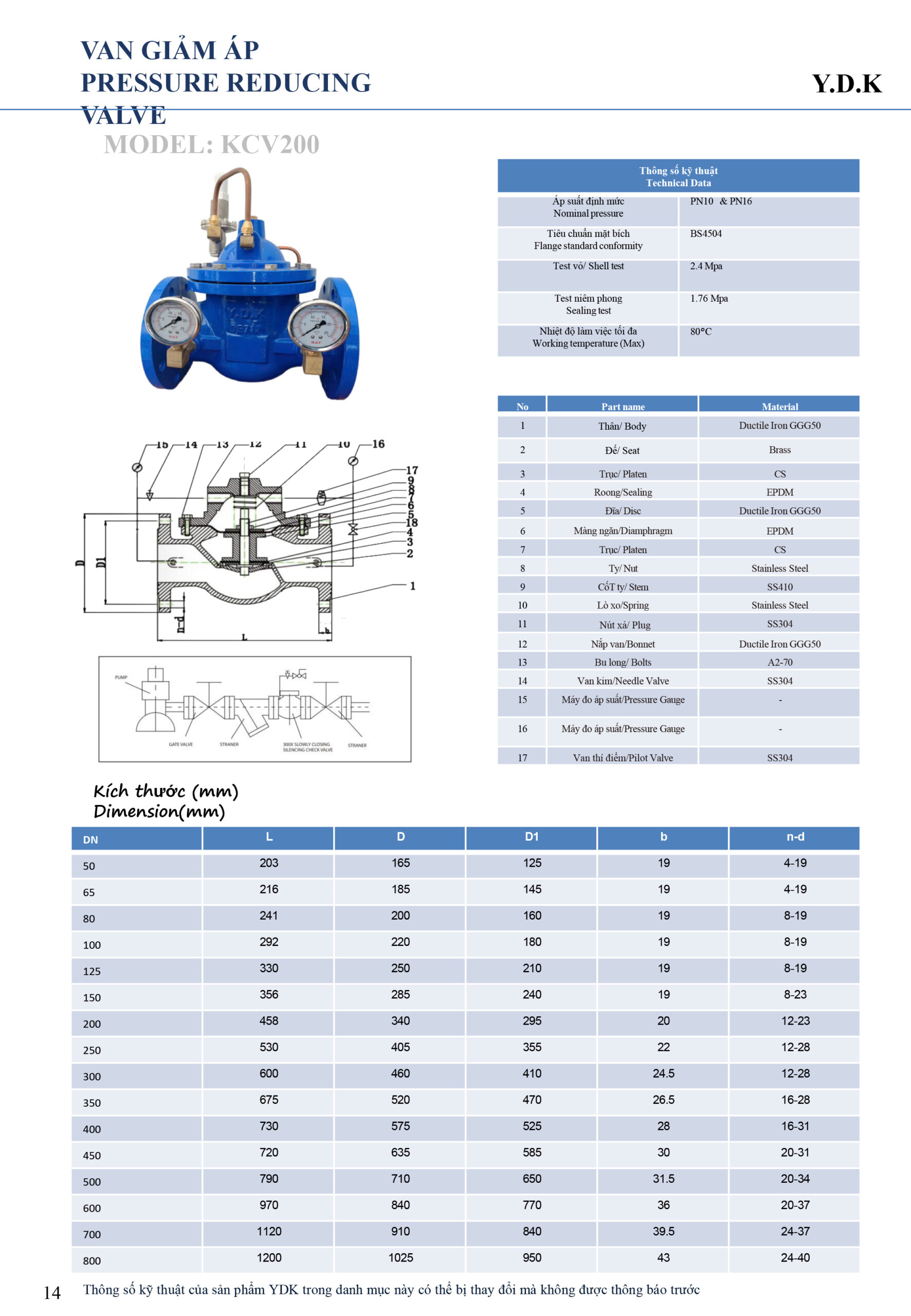
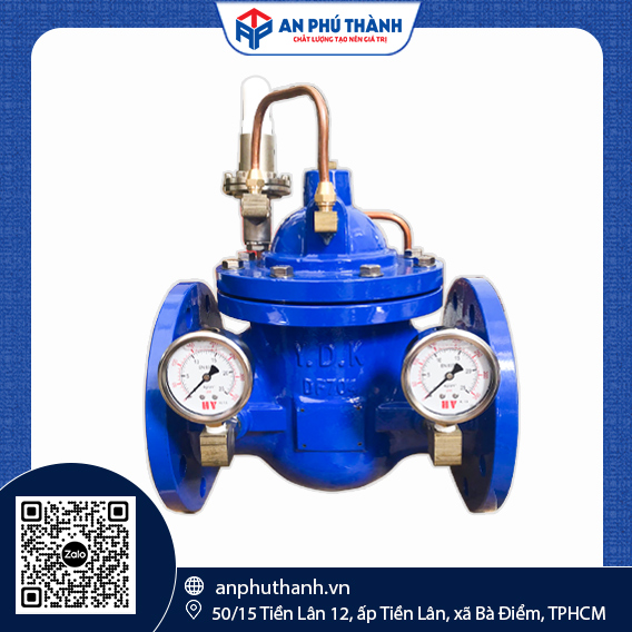
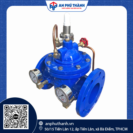
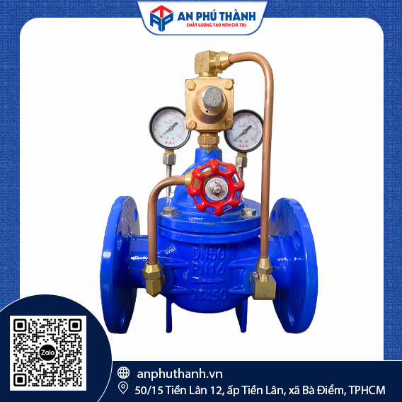
In high-rise buildings, domestic water supply pumping stations, and fire protection (PCCC) networks, fluid pressure on lower floors is often significantly higher due to differences in elevation head. The YDK Pressure Reducing Valve, Model KCV200, provides an automatic solution for regulating and maintaining stable downstream pressure at a preset value, protecting the piping system and downstream water-using equipment from the risk of excessive pressure.
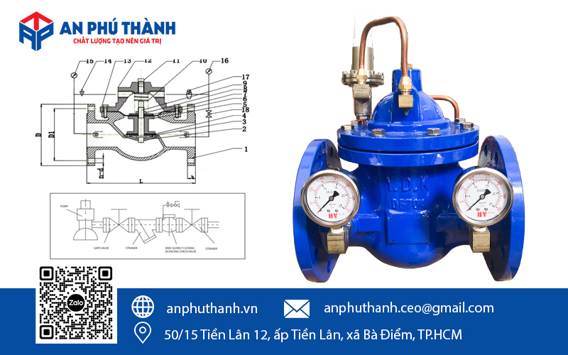
Like other hydraulic control valve series, the YDK pressure reducing valve has a relatively complex structure consisting of multiple components. Below are the 17 structural components taken directly from the Model KCV200 product catalogue:
| DN | L (mm) | D (mm) | D1 (mm) | b (mm) | n-d |
| 50 | 203 | 165 | 125 | 19 | 4-19 |
| 65 | 216 | 185 | 145 | 19 | 4-19 |
| 80 | 241 | 200 | 160 | 19 | 8-19 |
| 100 | 292 | 220 | 180 | 19 | 8-19 |
| 125 | 330 | 250 | 210 | 19 | 8 – 19 |
| 150 | 356 | 285 | 240 | 19 | 8 – 23 |
| 200 | 458 | 340 | 295 | 20 | 12 – 23 |
| 250 | 530 | 405 | 355 | 22 | 12 – 28 |
| 300 | 600 | 460 | 410 | 24.5 | 12 – 28 |
| 350 | 675 | 520 | 470 | 26.5 | 16 – 28 |
| 400 | 730 | 575 | 525 | 28 | 16 – 31 |
| 450 | 720 | 635 | 585 | 30 | 20 – 31 |
| 500 | 790 | 710 | 650 | 31.5 | 20 – 34 |
| 600 | 970 | 840 | 770 | 36 | 20 – 37 |
| 700 | 1120 | 910 | 840 | 39.5 | 24 – 37 |
| 800 | 1200 | 1025 | 950 | 43 | 24 – 40 |
The YDK pressure reducing valve operates based on automatic pressure differential control through the Pilot Valve assembly:
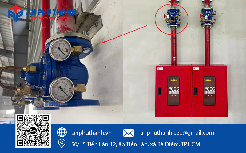
1. Bleeding Air from the Diaphragm Chamber: During initial installation or after maintenance, slightly loosen the air-release screw on the valve bonnet to completely remove air from the diaphragm chamber. Trapped air can cause the valve to “jerk” or result in unstable pressure reduction.
2. Pressure Adjustment Procedure on the Pilot Assembly:
3. Install a Y-Strainer Upstream: A Y-strainer must be installed upstream of the pressure reducing valve to prevent debris, sand, and other particles from entering the small passages of the Pilot assembly and causing blockages.
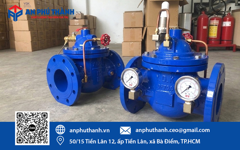
The experienced team at An Phu Thanh is always ready to provide consultation and quotations for YDK pressure reducing valves suitable for each customer’s project requirements. Contact us via Hotline/Zalo: 0946 729 913 for a prompt response.
Do you need product advice or a quote? Leave your details, and the technical team at An Phu Thanh will contact you within 24 hours.