

YDK Foot Valve | Model: KF-16
| Brand | Y.D.K |
| Model | KF-16 |
| Pressure Standard | PN16 |
| Brand | BTL |
| Origin | China |
| Nominal pressure | 1.0 MPa |
| Flange standard | BS4504 |
| Shell test | 1.0 MPa |
| Seal test | 0.55 - 1.0 MPa |
| Suitable medium | Water |
| Maximum working temperature | 80°C |
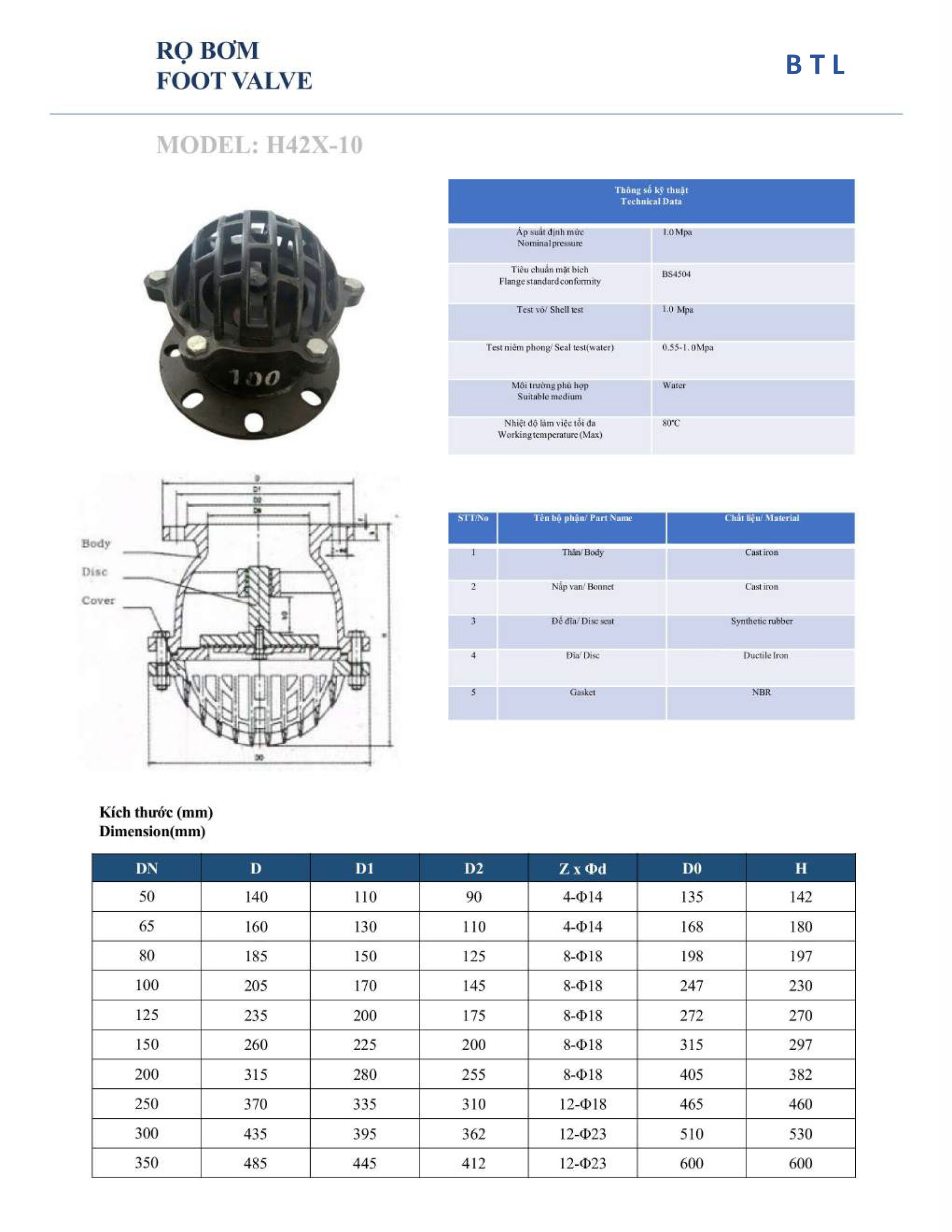
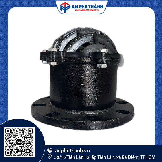
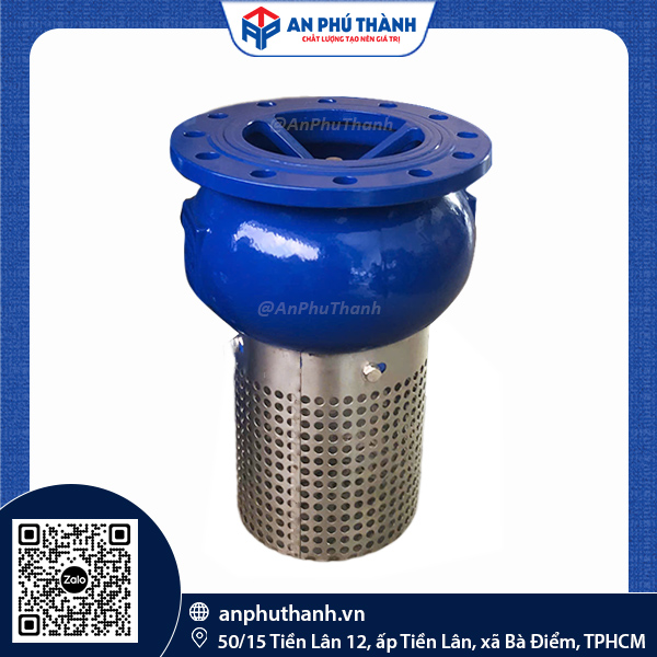
The BTL foot valve, Model H42X-10, is a specialized check valve installed at the end of the suction pipe in water pumping systems. This device performs two core tasks. First, it acts as a check valve, holding the water column in the pipeline when the pump stops, so the pump does not lose its prime. Second, its strainer section keeps large debris and sediment from entering and jamming or damaging the valve disc and the pump impeller.
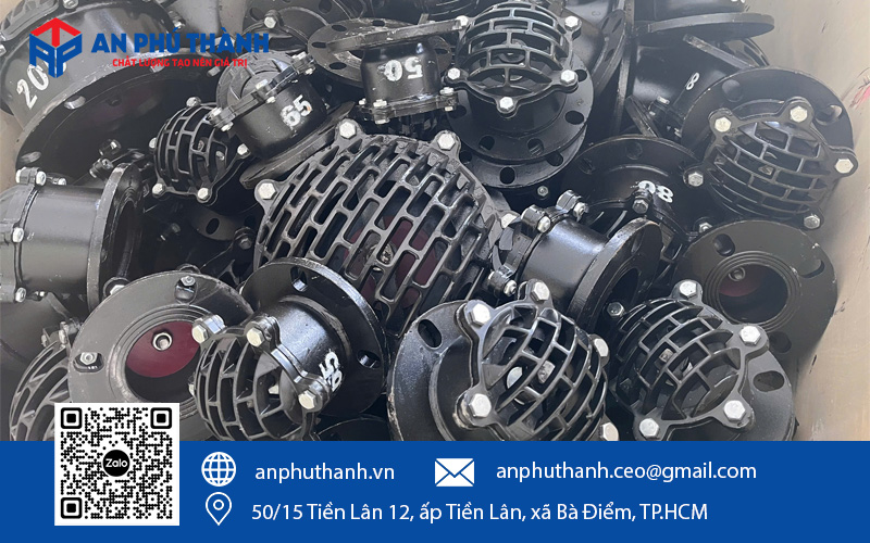
The BTL foot valve, Model H42X-10, has a simple mechanical construction, consisting of 5 main parts made from durable materials. You can refer to the table below for the construction, materials, and function of each part of the BTL H42X-10 foot valve:
| Component | Material | Function |
|---|---|---|
| Body | Cast iron | Valve shell with a flange for connection to the suction pipe, and also the support base for the entire internal mechanism |
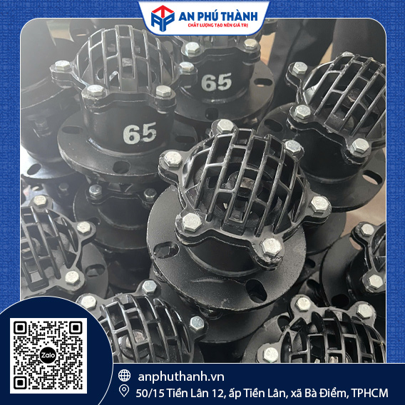
| Cover | Cast iron | Spherical strainer cage enclosing the lower part of the valve, which coarsely filters large debris and sediment before the fluid enters the valve |
| Disc seat | Synthetic rubber | Surface that contacts the disc when the valve is closed, ensuring tightness |
| Disc | Ductile iron | Main opening/closing element, moving vertically under the action of gravity and flow pressure |
| Gasket | NBR | Seals between the valve flange and the pipeline flange |
| DN | D (mm) | D1 (mm) | D2 (mm) | Z x Φd | D0 (mm) | H (mm) |
|---|---|---|---|---|---|---|
| 50 | 140 | 110 | 90 | 4 – Φ14 | 135 | 142 |
| 65 | 160 | 130 | 110 | 4 – Φ14 | 168 | 180 |
| 80 | 185 | 150 | 125 | 8 – Φ18 | 198 | 197 |
| 100 | 205 | 170 | 145 | 8 – Φ18 | 247 | 230 |
| 125 | 235 | 200 | 175 | 8 – Φ18 | 272 | 270 |
| 150 | 260 | 225 | 200 | 8 – Φ18 | 315 | 297 |
| 200 | 315 | 280 | 255 | 8 – Φ18 | 405 | 382 |
| 250 | 370 | 335 | 310 | 12 – Φ18 | 465 | 460 |
| 300 | 435 | 395 | 362 | 12 – Φ23 | 510 | 530 |
| 350 | 485 | 445 | 412 | 12 – Φ23 | 600 | 600 |
Notes:
The foot valve works on the principle of a lift check valve, opening and closing through gravity combined with a pressure difference.
When the pump starts, the suction creates negative pressure above the valve disc. This pressure difference overcomes the weight of the disc itself and lifts the disc off the disc seat, allowing the fluid to pass through the valve body and the strainer and move up the suction pipe into the pump.
When the pump stops, the suction pressure is lost, and the disc drops back to its original position under gravity, contacts the disc seat, and seals the pipeline. This sealing function keeps the entire water column in the suction pipe from flowing back to the source. It helps the pump stay primed for the next start-up, without having to be re-primed from scratch every time it runs.
The strainer cage surrounding the inlet prevents debris, large sediment, or foreign objects from getting into the valve and the suction pipe. It protects the valve disc from jamming, and protects the pump impeller from damage by foreign matter.
The foot valve is installed at the very end of the suction pipe, on the side submerged in the water source, such as a storage tank, well, pond, lake, or raw water pumping station. This is a mandatory position at the suction end. It is not installed at the discharge end like other ordinary check valves.
Because its opening/closing mechanism depends entirely on gravity, the foot valve may only be installed vertically, with the strainer end pointing down and the connecting flange pointing up and joined to the suction pipe. If installed tilted or horizontally, the disc cannot close fully because gravity no longer acts on it, leading to leakage or loss of prime when the pump stops.
The installation position must ensure that the foot valve is fully submerged in the water, at a sufficient distance above the bottom of the source to avoid sucking in settled sludge. At the same time, it must be at least a minimum depth below the water surface to avoid sucking in air, which causes cavitation in the pump.
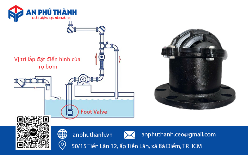
The BTL foot valve is commonly used in raw water intake environments from open sources, where the fluid may contain impurities, debris, or sediment and needs to be coarsely filtered before entering the pump system. Common application environments include:
Because the disc seat is made of synthetic rubber and the opening/closing mechanism is a gravity-driven lift type, the BTL foot valve is suitable for environments from clean water to moderately turbid water. It is not suitable for highly viscous fluids, strongly corrosive chemicals, or wastewater with a large content of solid waste, because these easily clog the strainer or jam the disc, reducing the suction flow or losing the ability to seal.
To receive consultation and a detailed quotation for a BTL – brand foot valve suited to your pump capacity and actual installation conditions, please contact An Phu Thanh via Hotline/Zalo OA: 0946 729 913. The An Phu Thanh team is always ready to support you quickly and attentively.
Do you need product advice or a quote? Leave your details, and the technical team at An Phu Thanh will contact you within 24 hours.